Magnetism and Electricity
Magnetic field about a wire carrying a current
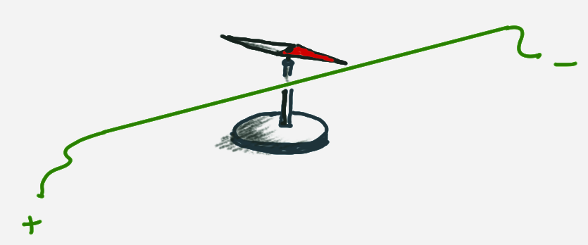
Hans Christian Oersted, a danish physicist conducted the following experiment in 1820. Oersted experiment -LeifiPhysik
Another experiment that followed from that:
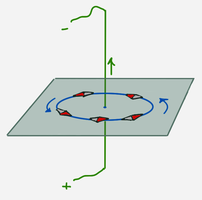
Around a wire with a current
The right hand can be used to determine the magnetic field about the wire. The thumb points in direction of the conventional current + –> -.
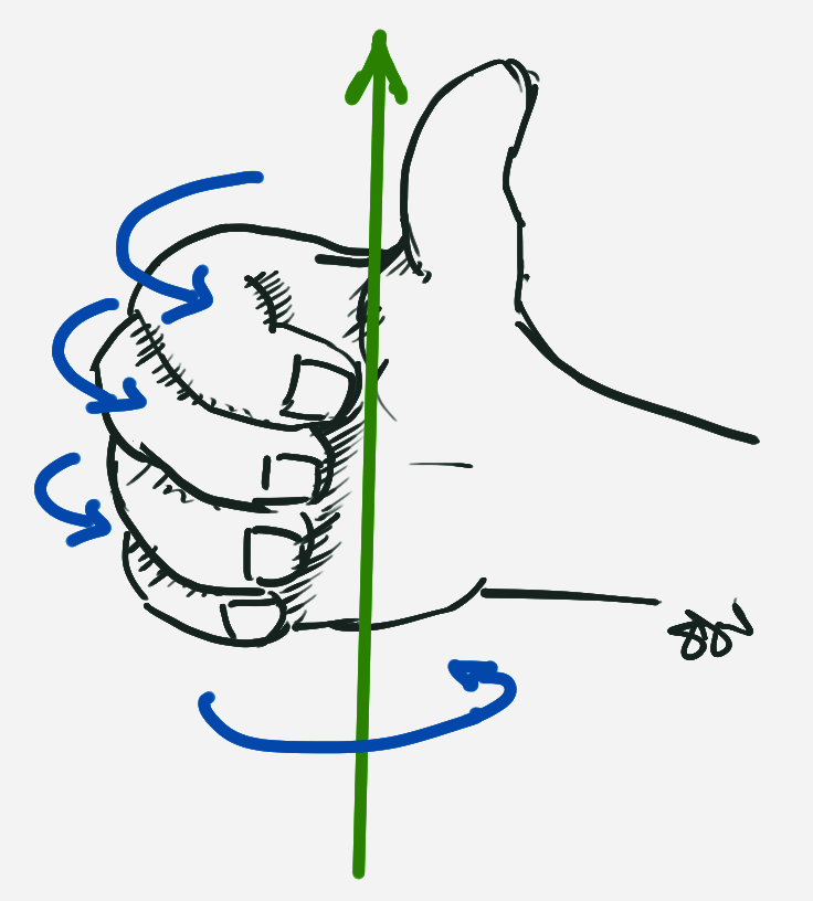
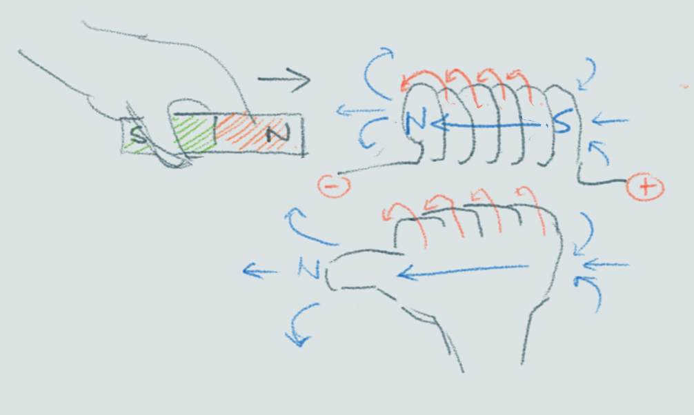
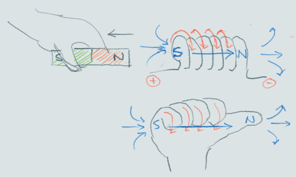
In a solenoid (coil)
This leads to the effect of a current through a coil of wire (solenoid) …
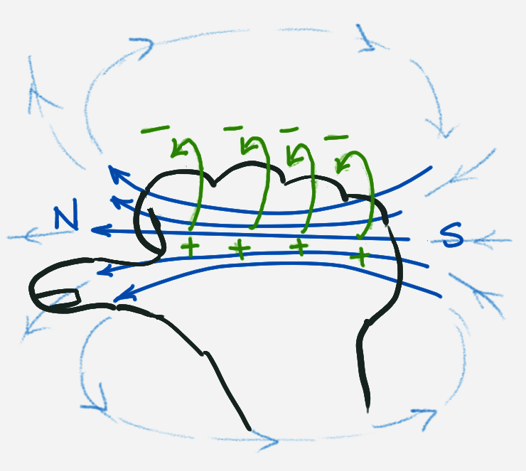
The fingers curl over in direction of the conventional current. The thumb points in direction of the North pole of the solenoid.
Lorentz force
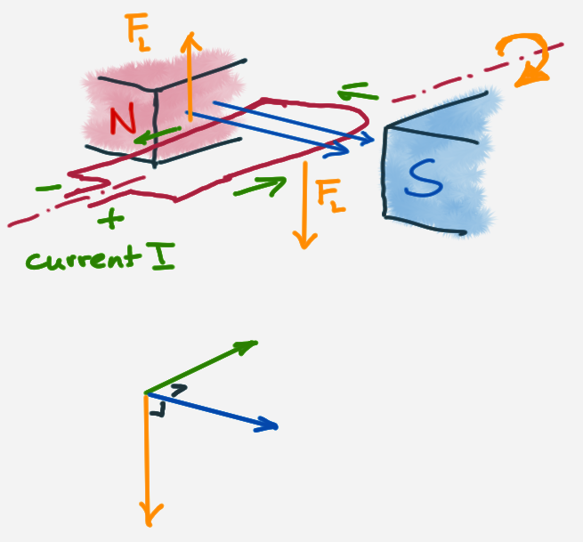
Question: What happens to the direction of the force after the coil makes a 180° rotation?
Right-hand (Mr Williams: “Why use the other hand?”)
After some contortions to get the hand into the correct position.
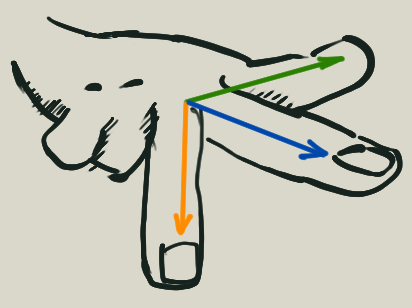
Comparing the right hand with the left hand.
- Thumb - conventional current + –> -
- Index finger - magnetic field N –> S
- Middle finger - direction of force
$F_L$
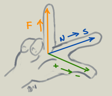
Flemming’s left hand rule for the same phenomena
- Thumb - Force
- Index finger - magnetic field dd
- Middle finger - direction of conventional current + –> -
Calculations
magnetic flux - magnetische Flussdichte
Experiments show that the force on a conductor in a magnetic field is directily proportional to:
- the magnetic flux density, B
- the current I, and
- the length l of the conductor in the field
$$F = B \cdot I \cdot l$$
or
$$B = \frac{F_L}{I \cdot l}$$ where $F_L$ is the German notation for the Lorentz force.
wire not perpendicular to the magnetic field
If the wire is not perpendicular to the magnetic field, but at an angle $\theta$ say, then the only the perpendicular component is considered and calculated as follows.
$$F = B \cdot I \cdot l \cdot \sin{\theta}$$
magnetic flux inside a long coil, influence of the material - magnetische Flussdichte im Inneren einer langen Spule, Einfluss von Materie auf die Flussdichte
$$B = \mu_0 \cdot \mu_r \frac{N \cdot I}{l}$$
B - magnetic flux density (magnetic field)
I - current (conventional direction)
$\mu_0$ - permeativity in a vacuum equal to $4\pi \cdot 10^{-7} Hm^{-1}$
$\mu_r$ - relative permeativity of material
N - number of turns in a coil (solenoid)
l - length of coil
Here is a table of magnetic permeability values of different materials which shows why an iron core will increase the magnetic field of a coil quite a bit as $\mu_r = 5000$ (or even 20000!! if 99.95% pure).
magnetic force on a moving charge
Lorentz force - LORENTZkraft
$$F_L = Q \cdot v \cdot B$$
- Q - charge (C)
- B - flux density (T)
- v - velocity (
$\frac{m}{s}$)
induction - Induktion
The electromagnetic effect can be reversed. That is, if a wire is moved in a magentic field or if a magnet is moved in a coil of wire (solenoid), then a current is induced. This is how we can generate electricity with movement.
experiment with magnet to show induction
Coil creates a North pole when the North of the magnet is moving towards the coil in order to repel the moving magnet.
Coil creates a South pole when the North of the magnet is moving away from the coil in order to attract the magnet away.
No relative movement means no current.
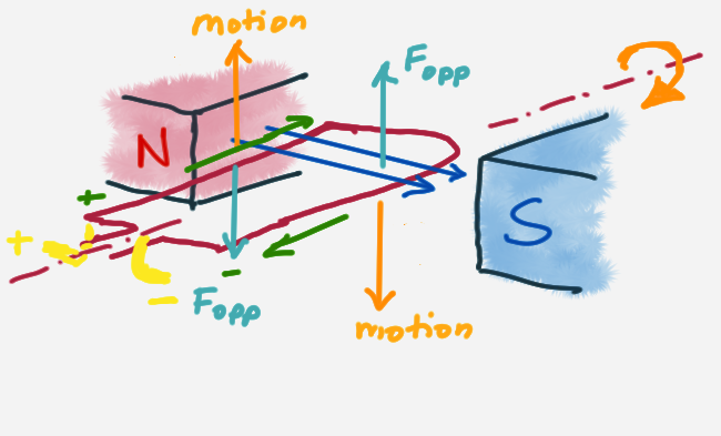
wire experiencing velocity in a magnetic field
The electrons moving in a direction with a velocity in a magnetic field act opposite to the direction of a positive charge (or conventional current) in the same magnetic field. Using the right-hand rule (or Flemming’s left hand rule) you can then determine the force acting on the electron. This results in the electrons moving in the wire. The conventional current generated is opposite to the induced motion of the electrons.
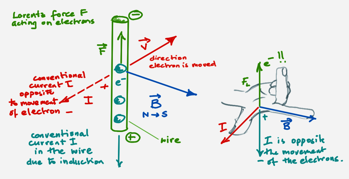
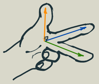
using the right-hand
after making sure the force is opposite the induced force (direction of motion of the wire). The Lorentz force opposes the motion causing induction.
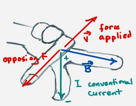
If we are to use the hands to determine the direction of the current, remember that induction causes a force opposite to the motion. If this is considered, the right-hand rule (Bavaria) is still valid or if you use Fleming, he switches the hands which in effect also reverses the force and gives the correct direction of the current due to induction.
Fleming’s hands
Having done physics in Bavaria, I am not so familiar with using Fleming’s hands. But here they are:
Faraday’s model on electromagnitic induction.
“The coil cuts through the lines of flux” then a current is induced in a wire.
Faraday’s law
Faraday found out that the induced current can be increased by:
- size of the magnet (stronger magnet)
- using a coil with more turns
- using a coil with a greater cross-sectional area
- moving the magnet faster
Lenz’s law
The direction of the induced current is such that it opposes the charge that produces it.
In a formula this is
$$U_{ind}= - N \frac{\Delta\Phi}{\Delta t}$$
where $\Phi = B \cdot A$.
The negative sign is to make clear that the emf ($U_{ind}$) due to induction is in opposite direction.
Magnetic Flux Linkage
$$\Phi = B \cdot A$$
In a coil with N turns:
$$\Phi = N \cdot B \cdot A$$
B - magnetic flux density (magnetic field) in Tesla (T)
A - area of region ($m^2$)
N - number of turns in a coil (solenoid)
$\Phi$ - magnetic flux
Eddy Currents - Wirbelströme
Experiments
- magnet in copper tube
- aluminium ring on coil
- plate swinging between a magnet
Self Inductance - Selbstinduktion
$$U_{ind}= - N \cdot A \cdot \frac{\Delta B}{\Delta t}$$
For a long coil:
$$B = \mu_0 \mu_r \frac{I \cdot N}{l}$$
$$U_{ind}= - N \cdot A \cdot \frac{\Delta ( \mu_0 \mu_r \frac{I \cdot N }{l} ) }{\Delta t}$$
as only the current varies:
$$U_{ind}= - \mu_0 \mu_r \frac{N^2 \cdot A}{l} \cdot \frac{\Delta I }{\Delta t}$$
$$U_{ind}= - L \cdot \frac{\Delta I }{\Delta t}$$ where L is inductivity
$$L = \mu_0 \mu_r \frac{N^2 \cdot A}{l}$$
I - current (conventional direction)
$\mu_0$ - permeativity in a vacuum equal to $4\pi \cdot 10^{-7} Hm^{-1}$
$\mu_r$ - relative permeativity of material
l - length of conductor
L - inductivity
$U_{ind}$ - electromagnetic force (emf or EMF)
Note that in German speaking countries the potential difference is denoted by U as V is the unit and also V is generally used for volume.
example - coil (square cross-section)
l = 20 cm, edge length = 5 cm, N = 1000 turns , $\mu_r$ = 300
Find the inductivity L.
Solution (link)
switching on a coil
circuit diagram
I-t diagram
U-t diagram
Generator
With a generator we reverse the function of a motor and created a current flow. Applying Lenz’s law the direction is opposite to that in a motor.
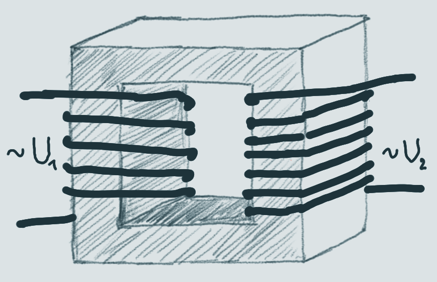
Transformer - der Transformator
An alternating current switches direction from plus to minus and back at a given frequency (in Germany the mains supply is ).
A transformer is made of two coils on a soft iron core next to each other with seperate circuits. As the current is constantly changing in the first coil, a current is induced to the second coil (according to Lenz’s law).
The voltage induced depends on the ratio of the number of turns between the two coils.
The two coils are referred to as primary coil (Primärspule) and secondary coil (Sekundärspule).
In the primary coil:
$$U_1 = -N_1 \cdot \frac{\Delta \Phi}{\Delta t}$$
and in the secondary coil:
$$U_2 = -N_2 \cdot \frac{\Delta \Phi}{\Delta t}$$
Substituting $\frac{\Delta \Phi}{\Delta t}$ of the first equation into the second we get.
$$U_2 = -N_2 \cdot -\frac{U_1}{N_1}$$
Rearranging, we get.
$$\frac{U_1}{U_2} = \frac{N_1}{N_2}$$
Step up - step down
Power supplied
$$P_1 = P_2$$
$$I_1 \cdot U_1 = I_2 \cdot U_2$$
$$\frac{U_1}{U_2} = \frac{I_2}{I_1} $$
For a strong ideal transformer we have:
$$\frac{I_1}{I_2} = \frac{N_2}{N_1} $$